Pikku Dial - Multimode Dial Controller Powered by RPi Pico
Designed a small open-source multimode USB dial controller powered by Raspberry Pi Pico. Code is highly customizable. STL files available.

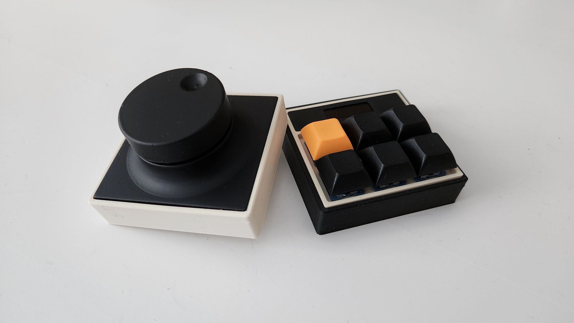
Designed a small USB dial controller to fit together with its predecessor, the Pikku Macropad. The Dial also uses Raspberry Pi Pico and is even simpler under the hood as the only component in addition to Pico is KY-040 rotary encoder. The rotary encoder includes a switch action in addition to rotary function so pushing it will switch between different modes that you can easily customize in Python code.
The modes I have there currently are:
- Volume
- Scroll (mouse-wheel up/down)
- Arrow keys up/down (like moving a cursor up/down or scroll in smaller steps)
- Fidget mode (does nothing, a stress toy 😀)
TL;DR: Check the GitHub repository for code: github.com/tlaukkanen/pikku-macropad. 3D printable .stl models are also available via Printables.com
Bill of Material
Components needed to build your own dial controller:
- Raspberry Pi Pico
- KY-040 rotary encoder (I used these from Amazon.de)
- 3D printed case
Hardware - 3D Printed Case
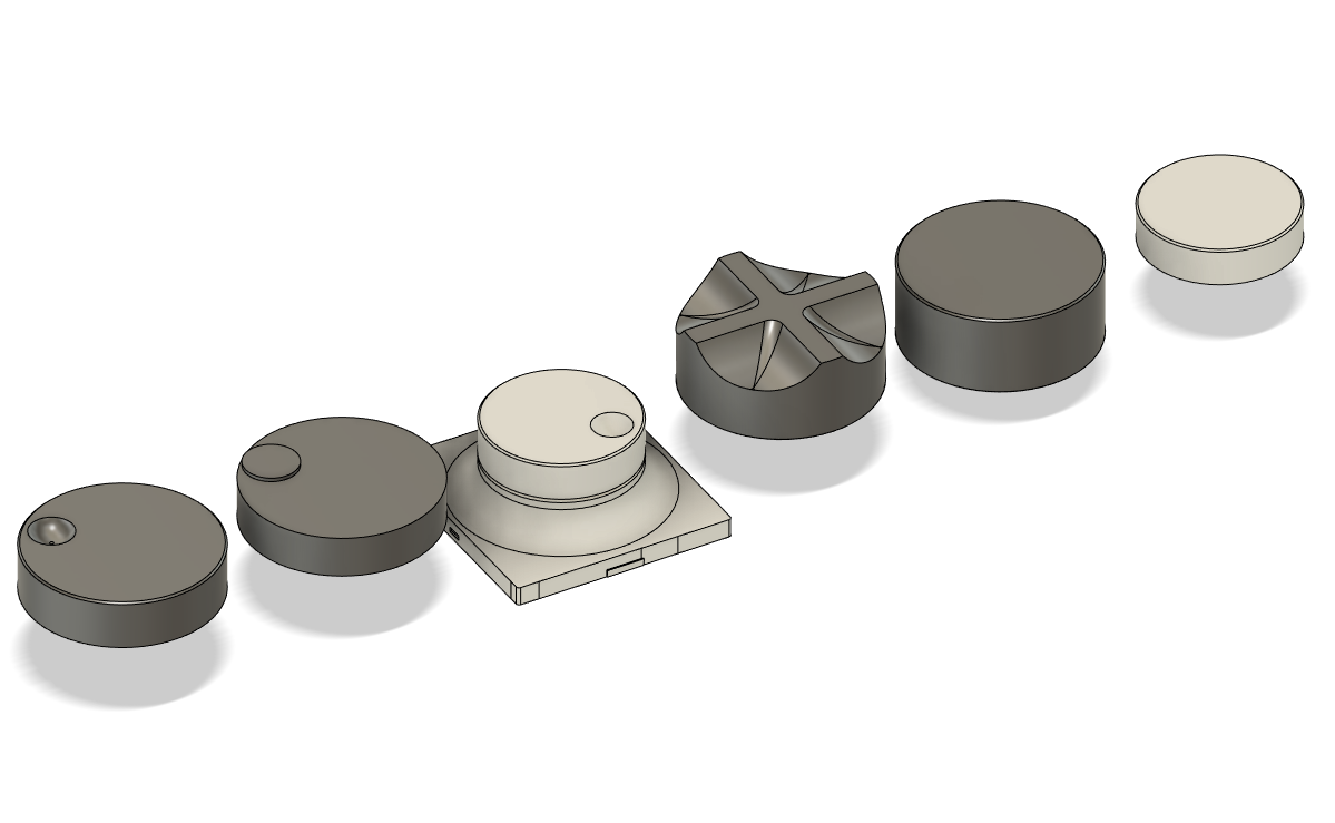
I designed the case to be simple and easy to print. It consists of four layers where the base houses the Raspberry Pico (same as in macropad), the second layer holds the rotary encoder in place on top of Pico. The third layer is the top panel enclosure and the last one is the actual dial knob that is connected to rotary encoder.
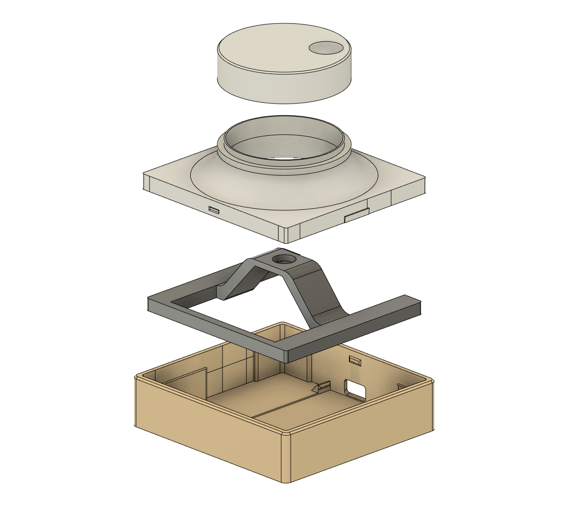
You can print parts with assorted colors to have different looks depending how you want it to look and to differentiate or make it use similar colors as your macropad.
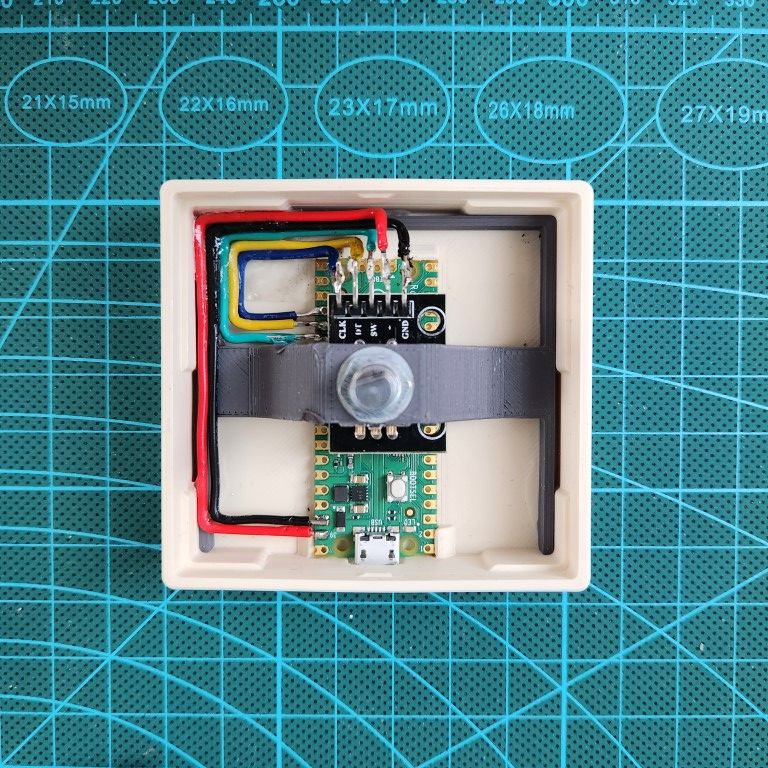
I used some super glue to put the second layer in place with the rotary encoder. It shouldn't need it necessarily as there are only applied forces downwards when rotary is pressed.
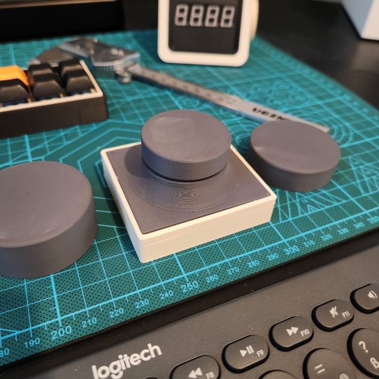
Have Fun with Dial Knobs
You can quite easily design your own rotary knobs and try to find the one that suits you the best. I found the dial knobs with small "slot" for a finger to be nice.
Improvement Ideas for the Case
There are couple of ideas that could improve the usability a bit: weight and smaller rotary ratio, meaning that it could have gearing so that rotary encoder would rotate faster with smaller movement. Now it's over 10° angle for each step. Something like 2:1 - 4:1 gear ration in between the dial and encoder could feel better.
The case is quite light so rotating the dial can easily rotate the case too. Some weight could be added by adding some metal pieces to the empty slots in the case.
Schematics and Soldering
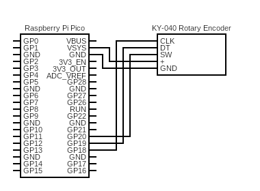
The wiring is simple as you only have the Pico and rotary encoder. Wire the power from Pico's VSYS to + in KY-040. GND ground to GND ground of KY-040.
Depends on your code wire the GPIO pins in the following way (or choose your own):
- GPIO PIN 20 to SW (Switch)
- GPIO PIN 19 to DT
- GPIO PIN 18 to CLK
Code
I flashed the Raspberry Pi Pico with the latest CircuitPython firmware by following this "Getting started with CircuitPython" tutorial from Adafruit. For code I used CircuitPython libraries:
- adafruit-circuitpython-hid for keyboard and mouse communication
Here's the full code for the macropad. Code can also be found from GitHub, here.
import board
import digitalio
import rotaryio
import time
import usb_hid
import adafruit_hid.keyboard as keyboard
import adafruit_hid.mouse as mouse
from adafruit_hid.keyboard_layout_us import KeyboardLayoutUS
from adafruit_hid.keycode import Keycode
from adafruit_hid.consumer_control import ConsumerControl
from adafruit_hid.consumer_control_code import ConsumerControlCode

# Define pins
DT_PIN = board.GP19
CLK_PIN = board.GP18
SW_PIN = board.GP20

BTN_DOWN = 1
BTN_UP = 0

button = digitalio.DigitalInOut(SW_PIN)
button.direction = digitalio.Direction.INPUT
button.pull = digitalio.Pull.DOWN
last_button_state = BTN_UP
last_position = None

# Define initial mode
mode = "VOL"

# Define keyboard layout
pikku_keyboard = keyboard.Keyboard(usb_hid.devices)
layout = KeyboardLayoutUS(pikku_keyboard)
cc = ConsumerControl(usb_hid.devices)
pikku_mouse = mouse.Mouse(usb_hid.devices)

# Define rotary encoder callback function
def change_mode():
    global mode
    if mode == "VOL":
        mode = "SCROLL"
    elif mode == "SCROLL":
        mode = "CURSOR"
    elif mode == "CURSOR":
        mode = "FIDGET"
    else:
        mode = "VOL"
    time.sleep(0.1)

# Define rotary encoder reading function
def read_encoder(encoder):
    global last_position
    position = encoder.position
    if last_position == None or position == last_position:
        last_position = position
        return 0
    delta = last_position - position
    last_position = position
    return delta

# Create rotary encoder object
encoder = rotaryio.IncrementalEncoder(DT_PIN, CLK_PIN)

# Define main loop
while True:
    # Read rotary encoder
    encoder_delta = read_encoder(encoder)
    if encoder_delta != 0:
        print("delta: " + str(encoder_delta))

    # Adjust volume, scroll or cursor based on mode
    if mode == "VOL":
        if encoder_delta > 0:
            cc.send(ConsumerControlCode.VOLUME_INCREMENT)
        elif encoder_delta < 0:
            cc.send(ConsumerControlCode.VOLUME_DECREMENT)
    elif mode == "SCROLL":
        if encoder_delta > 0:
            pikku_mouse.move(wheel=-1)
        elif encoder_delta < 0:
            pikku_mouse.move(wheel=1)
    elif mode == "CURSOR":
        if encoder_delta > 0:
            pikku_keyboard.send(Keycode.DOWN_ARROW)
        elif encoder_delta < 0:
            pikku_keyboard.send(Keycode.UP_ARROW)
    else:
        # Fidget mode - do nothing
        if encoder_delta > 0:
            print("right")
        elif encoder_delta < 0:
            print("left")

    # Check if rotary encoder switch is pressed
    if button.value is False and last_button_state == BTN_UP:
        change_mode()
        print("new mode: " + mode)
        last_button_state = BTN_DOWN
        time.sleep(0.1)
    else:
        last_button_state = BTN_UP

    # Delay to avoid debounce
    time.sleep(0.02)
Have fun on building your own! Remember to post your make on Printables :)
Join the discussion in Mastodon: